Injection Molded Toy
As the culminating project for ENGR3260 Design for Manufacturing, I worked with a part to design, a plastic injection molded toy. This included designing the part, CNC machining the molds and operating a manual injection molding machine to create the final part. In this process we practiced tolerancing, designing with draft angles, running plastic flow simulations to place runners and sprues, and optimizing for assembly.

Skills
Tolerencing
Design for Assembly
Prototyping
CNC Machining
Injection Molding
SolidWorks Plastics
Toy Design
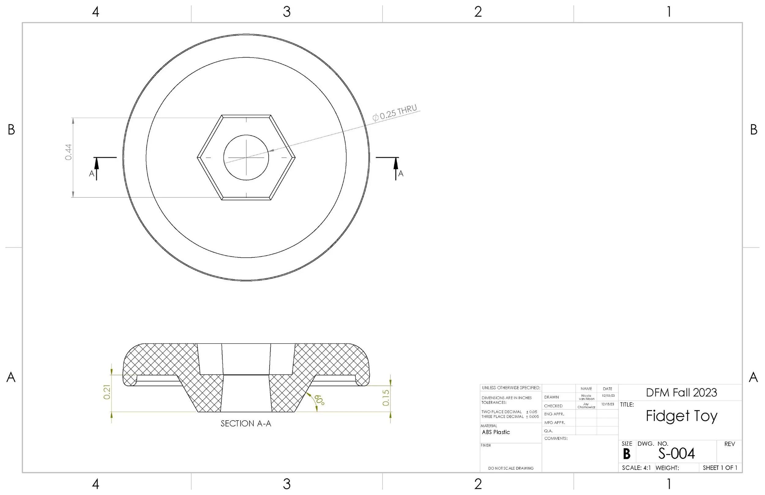
Our inspiration was to create a fidget toy that mimicked the classic cat ball in a ring toy but at a scale that it would comfortably fit in a person’s hand. Our design goals to achieve this included keeping the ball securely inside the track, ensuring smooth ball rolling, creating a comfortable and ergonomic size and shape, and achieving fast, inexpensive manufacturing.


We succeeded in ensuring smooth rolling by using off-the-shelf ball bearings as the ball due to its consistency in size and shape. We also designed an internal profile that strategically constrained the ball with a smaller opening than the ball’s diameter but with flat edges to minimize the points of contact between the ball and the track so that there would be less surface contact and the surface finish and consistency of the internal track surfaces would be less critical.
The final product, with a 1.25-inch diameter and rounded corners for comfort, not only met ergonomic expectations but also proved cost-effective, with consumable materials averaging around $0.60 per unit for mid-scale production. This successful integration of design and manufacturing considerations underscores the project's effectiveness in delivering a functional, user-friendly, and economically viable fidget toy.
Design for Manufacturing

Design For Assembly
To make assembly simple, we utilized a single bolt to connect the two sides. Initially, we were planning to use a countersunk cap screw. However, we redesigned the toy to work with a hex-hed screw so that we could eliminate the need for any tooling in assembly. Instead, the hexagonal cavities on each side of the mold hold the bolt head and nut respectively allowing the twisting of the two halves relative to each other to tighten or loosen the connection. This also enabled us to make both halves of the track identical. which further simplifies both the manufacturing and assembly.

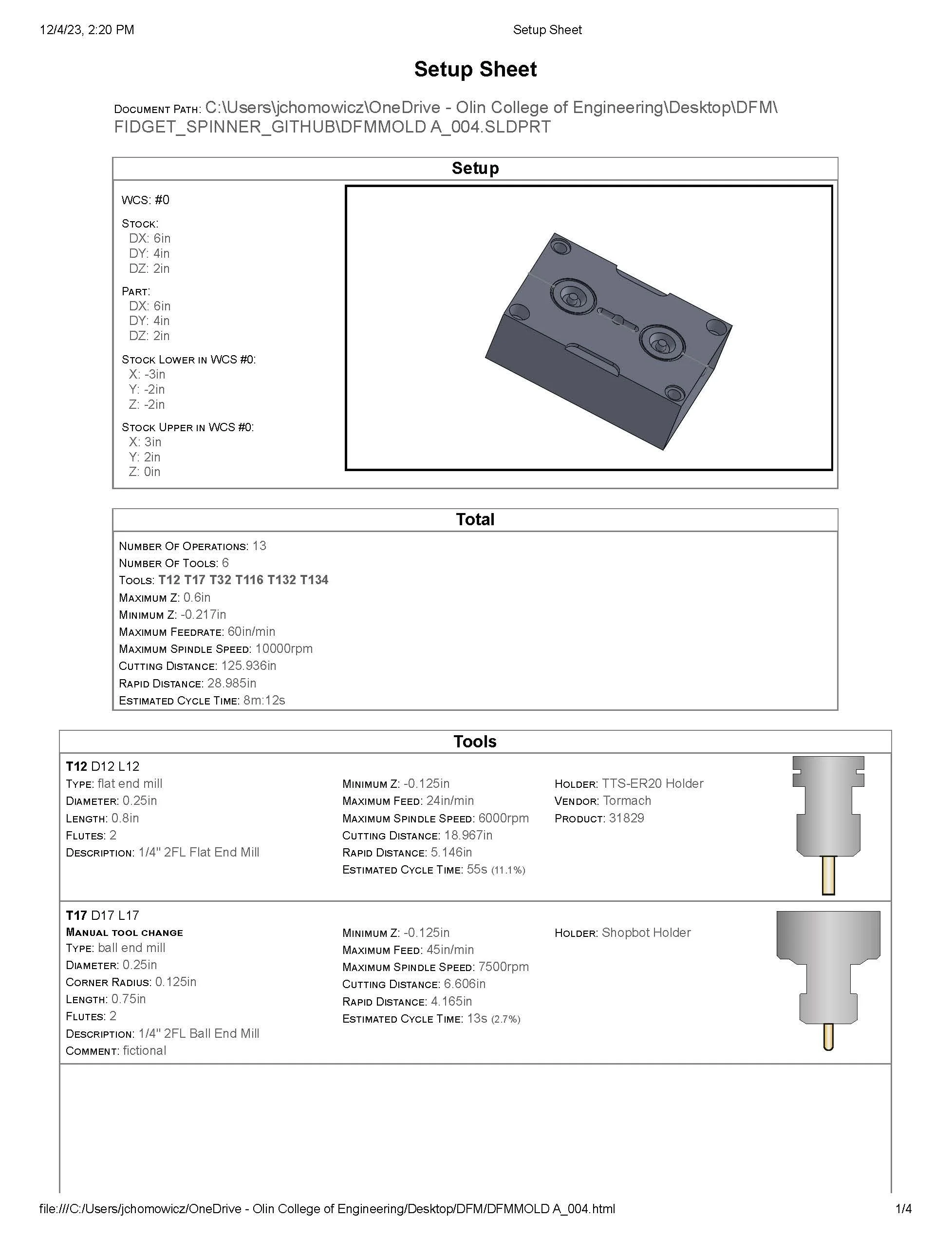
Mold Block Design
When turning our initial product into a mold design for machining, we redesigned our initial mold to utilize a simpler planer parting line so that we would not have to machine down the original faces on either of our mold blocks. This change required that we adjust the length and draft angles on some features but dramatically reduced the machining time and complexity of our mold creation.

Runner Placement
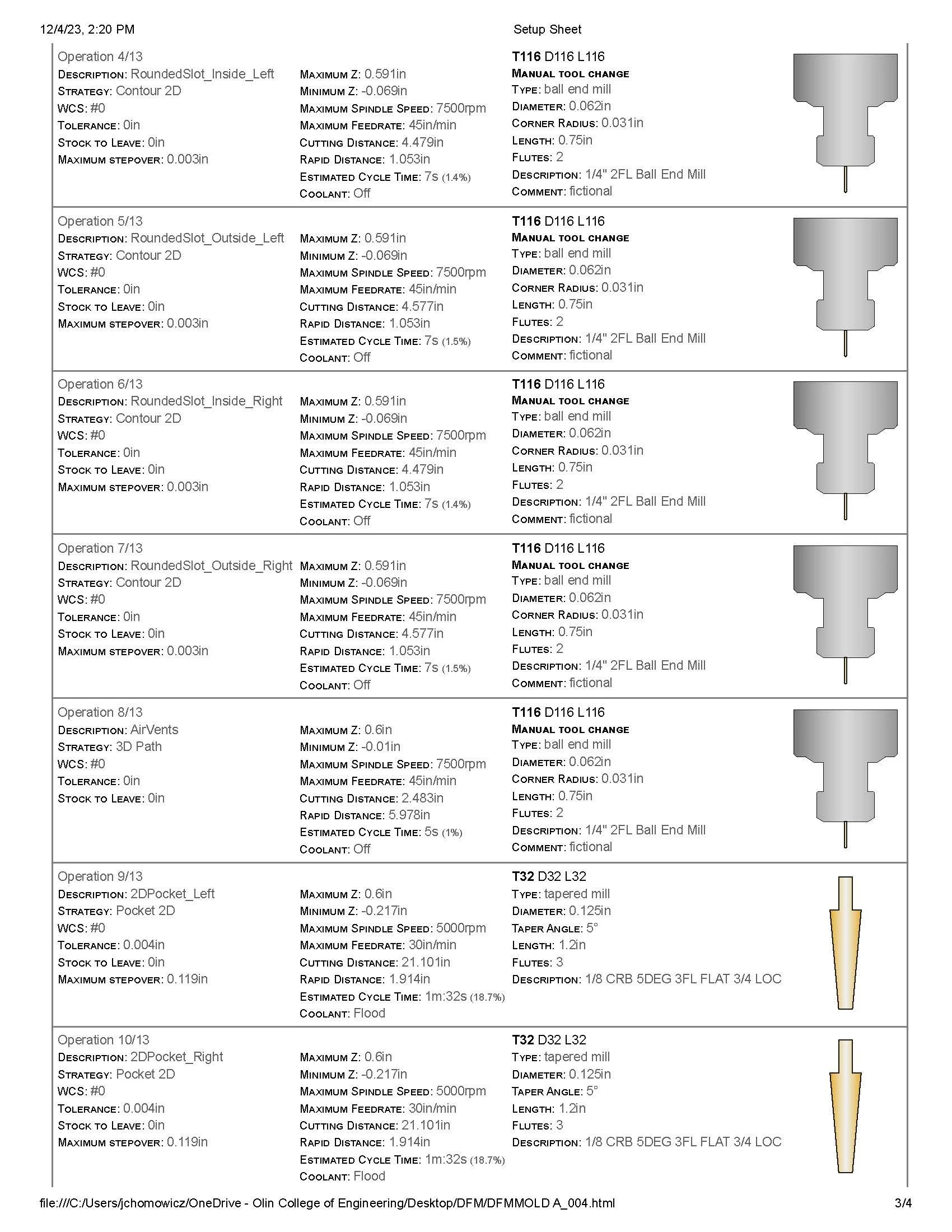
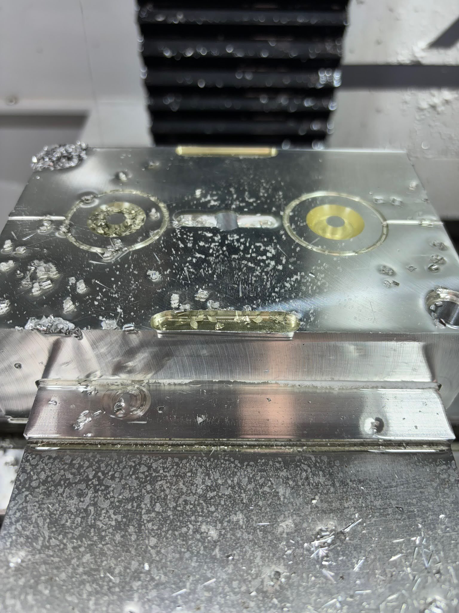
We analyzed two runner designs, one that filled the part from two sides at once and one that just filled from one side. We decided to go with the single center runner design as it only created one weld line and we did not have to add any complicated vent holes to allow trapped air to escape from the enclosed center of the part. This also reduced the volume of waste plastic in the runners.
Machining
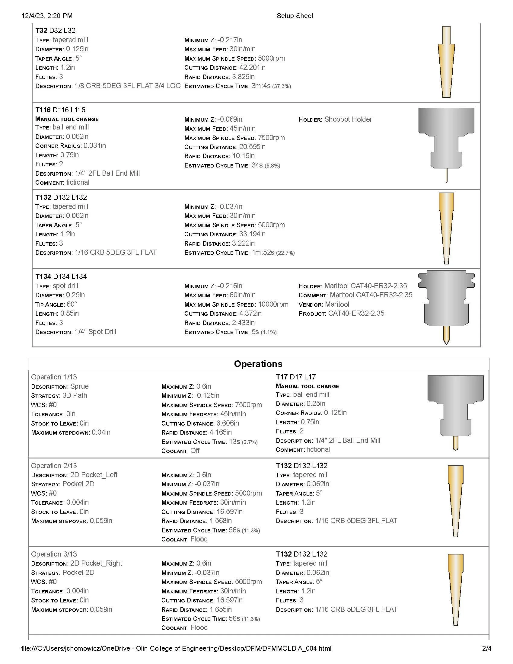
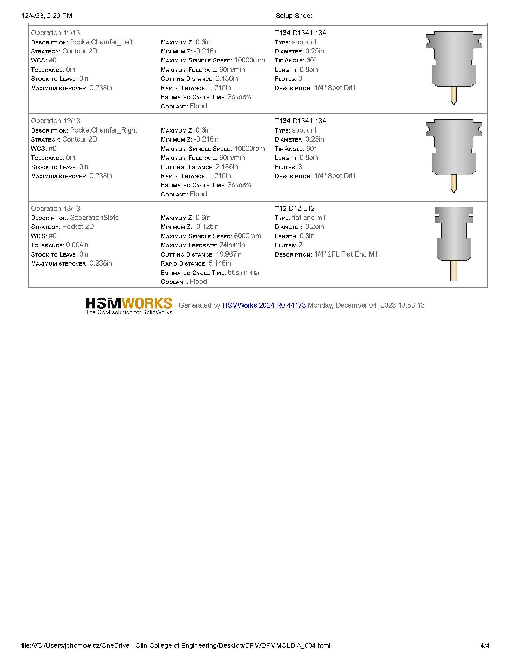
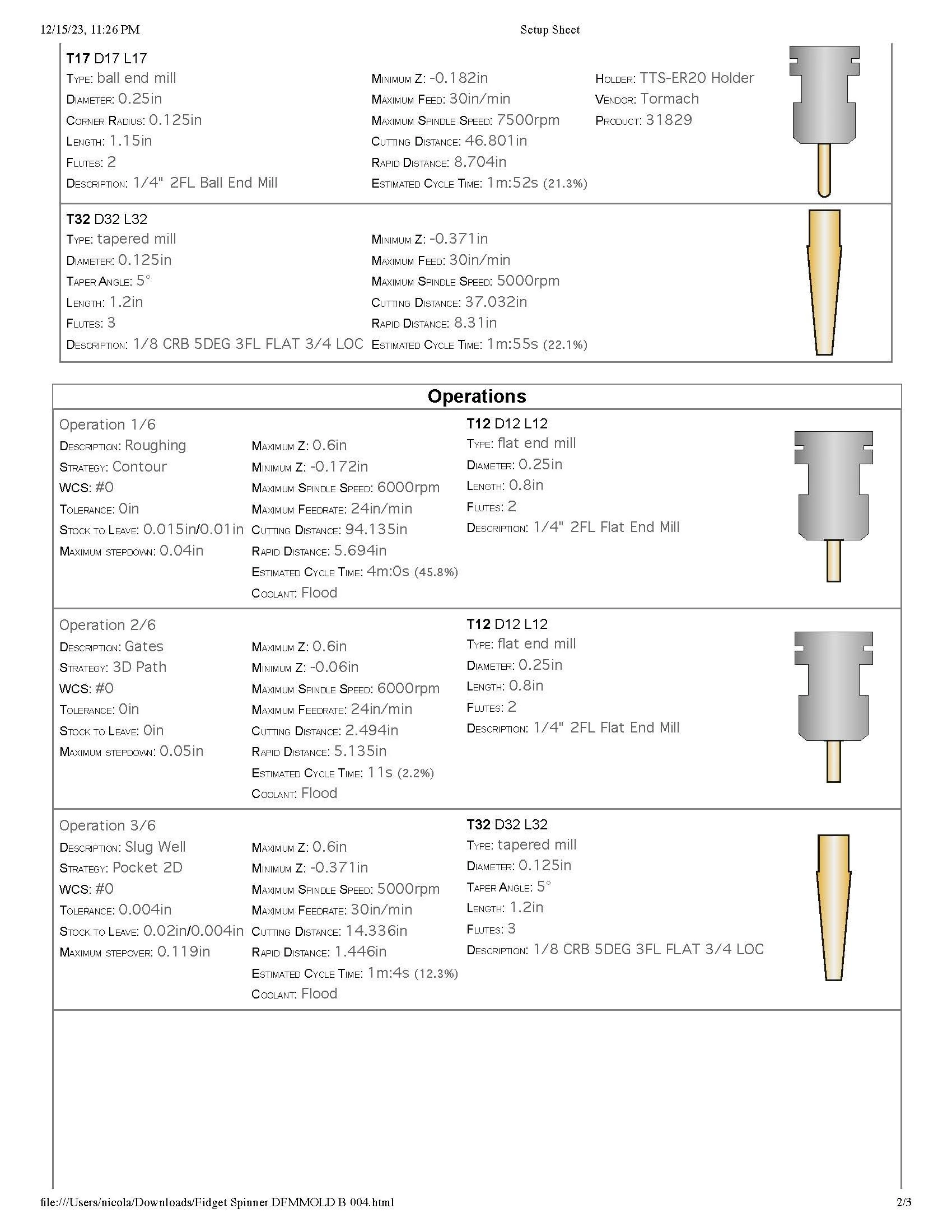
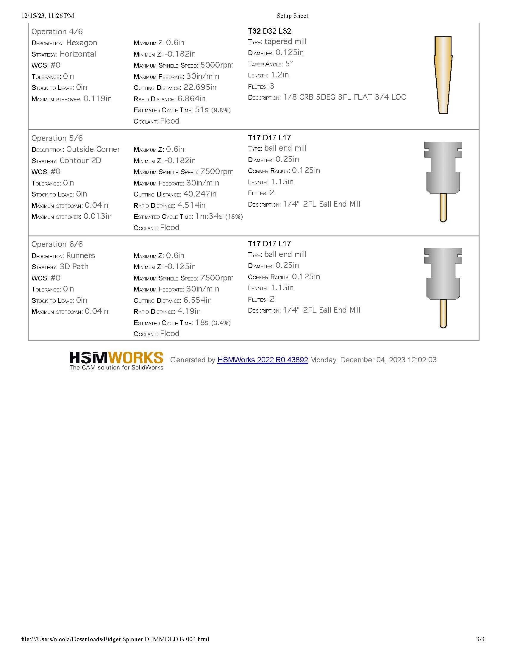
We refined the geometry of our mold to be able to be machined with only 6 tool changes. We also optimized to use a 1/4 inch end mill to do the majority of our material removal which kept our total machining time down.
In order to achieve the thin slot needed to mold the rim that holds the ball within the track, we used 2, 1/16 inch diameter tools. A tapered tool to achieve the necessary 5 degree draft angles, and a ball end mill to round off the surface. The use of these two tools kept us from needing custom tooling. Additionally since the 1/16 inch bits were only needed to create this small pocket, we were able to run the tools quite conservatively without dramaitically increasing our machining time as to not risk tool breakage with such a small tool.
The top half had a cycle time of just over 10 minutes, and the bottom half had a cycle time of
With the setup, tool changes, and reduced feed rates at critical moments, the total machining took us around an hour and a half.

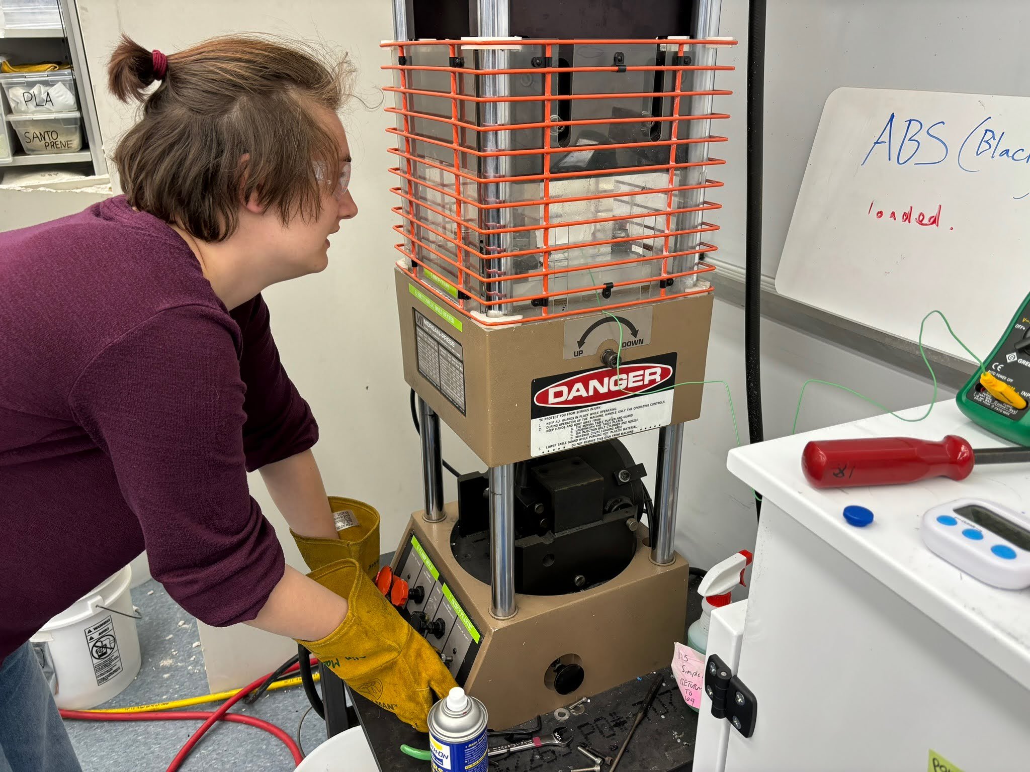
Injection Molding
We injection molded with ABS in a manual injection molding machine. The optimal settings we found were to use a clamping force of 12, with an injection pressure of 6 PSI for 2.5 seconds. With as small of a mold volume as we had and a hole in the center of our part the precision of our, injection that to be quite precise. When we filled for 2.25 seconds or less, we did not get a full fill of our part which produces an unfit part as the ball will escape the track through this defect. If we injected for 2.75 seconds or more we observed flashing. This flashing plugged the whole needed for the center bolt making the part unviable at 3 or more seconds.
Despite honing a precise ideal duration for injection, we struggled with precisely releasing the injection knob at the correct time. An automatic timing feature would greatly improve the reliability of our manufacturing process and our viable part yield. With our current struggles, we ended up with 3 ideal parts, and 7 viable parts, and 20 unusable parts. To improve our design for the same machine we could consider further increasing the size of our airvents — to almost create an outlet gate and runner — so any excess plastic has a place to flow without causing flashing that will be easy to remove after the part cools.

Cost Analysis
While the consumables for each toy only cost $0.60, the upfront cost of creating the injection mold is nearly $400. Including an assembly time of 100 per hour, each toy costs around $1.50 to manufacture if they are made on a scale of 1000.
This low manufacturing cost would allow the toy to be sold at a reasonable price point in the $3-5 range.


Manufacturing Report