
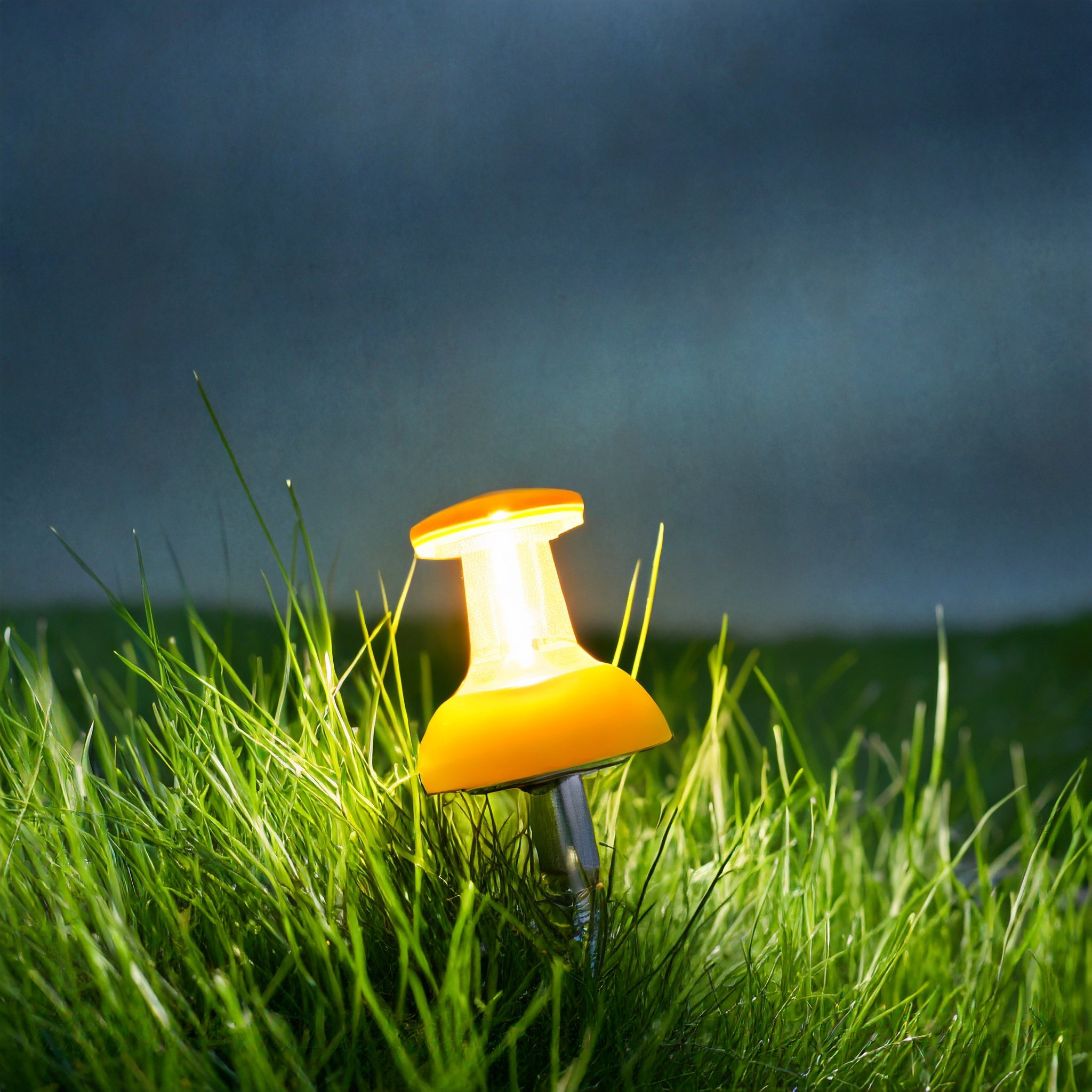
GlowPin Nightlight
The GlowPin celebrates the art of magnifying small objects by presenting a luminous nightlight in the iconic pushpin shape, utilizing design for manufacturing principles and functional design elements. The final form is fabricated using a urethane cast base and vacuum-formed pushpin head.
Design
The design of GlowPin is intended to fit within a collection of enlarged everyday objects, transforming them into striking, larger-than-life creations. Mimicking the aesthetics of minuscule commonplace items like tiny milk crates and towering caution cones, the objective was to maintain the unmistakable shape and essence of a pushpin while scaling it up to the size of a nightlight. This meant emphasizing a slender stem, a translucent bulb and a subtle seam along the edge to match the parting line seen on pins. The base needed to seamlessly integrates with the design, making the light appear self-standing without distracting or noticeable elements.
Components

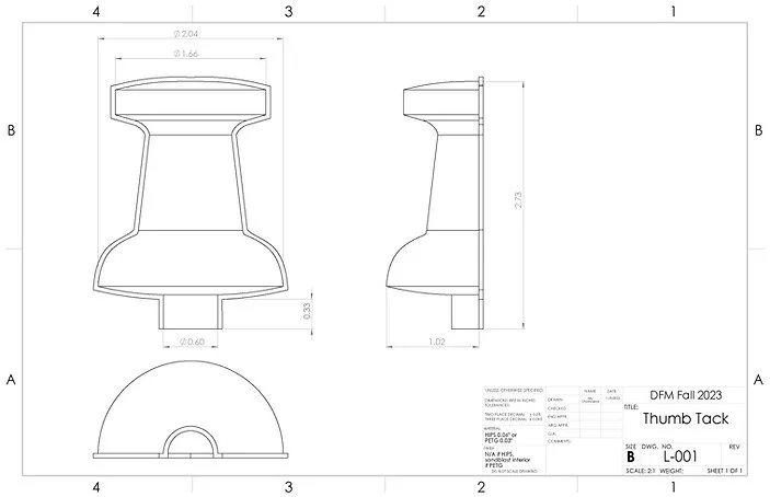
Pin Head
Iconic Shape: The pinhead embodies the iconic pushpin shape, maintaining the recognizable form in its design.
Subtle Seam: Featuring a discreet seam along the edge, mimicking the characteristic parting line of a classic pushpin.
Light Diffusion: Engineered to diffuse light, ensuring a soft and ambient illumination.

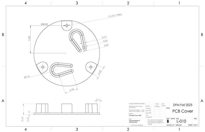
Lamp Base
Housing & Accessibility: Serves as the housing for the PCB while enabling convenient access for battery change and button interaction.
Stabilization: Designed to stabilize the lamp, ensuring a secure and balanced foundation.
Unobtrusiveness: Emphasizes simplicity, offering a visually unobtrusive design to keep focus on the pin head.
Stem and PCB
Sturdy Construction: Ensures structural strength and durability to support the overall design.
LED Passage: Accommodates the LEDs, allowing them to travel through to illuminate the bulb.
Slim Design: Engineered to resemble the thin aspect of a pushpin, presenting a slender and aesthetically faithful element.
Manufacturing Process

Vacuum Forming
The two halves of the GlowPin were created with vacuum-formed transparent PETG or colored HIPS. This manufacturing process ensured the final product remained translucent and lightweight, preserving the essence of the pushpin's aesthetic. By splitting the pushpin vertically into 2 halves we can achieve the desired pushpin shape while eliminating any overhangs and providing a generous draft angle on all surfaces. Moreover, the division between the two halves was purposefully designed to resemble the parting line seen in classic formed pushpins, adding to the authenticity of the design.

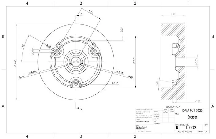
Urethane Casting
The GlowPin components were manufactured through a urethane casting process, utilizing silicone molds derived from 3D-printed parts. The process involved carefully pouring urethane resin into the molds, allowing it to cure to form the desired components. Modifications, such as adding draft angles, internal fillets, and replacing holes with alignment indents, were made to the 3D model to facilitate successful casting. These alterations ensured consistent replication and streamlined the production of base and cover components, enhancing the overall quality and repeatability of the manufacturing process.

Assembly
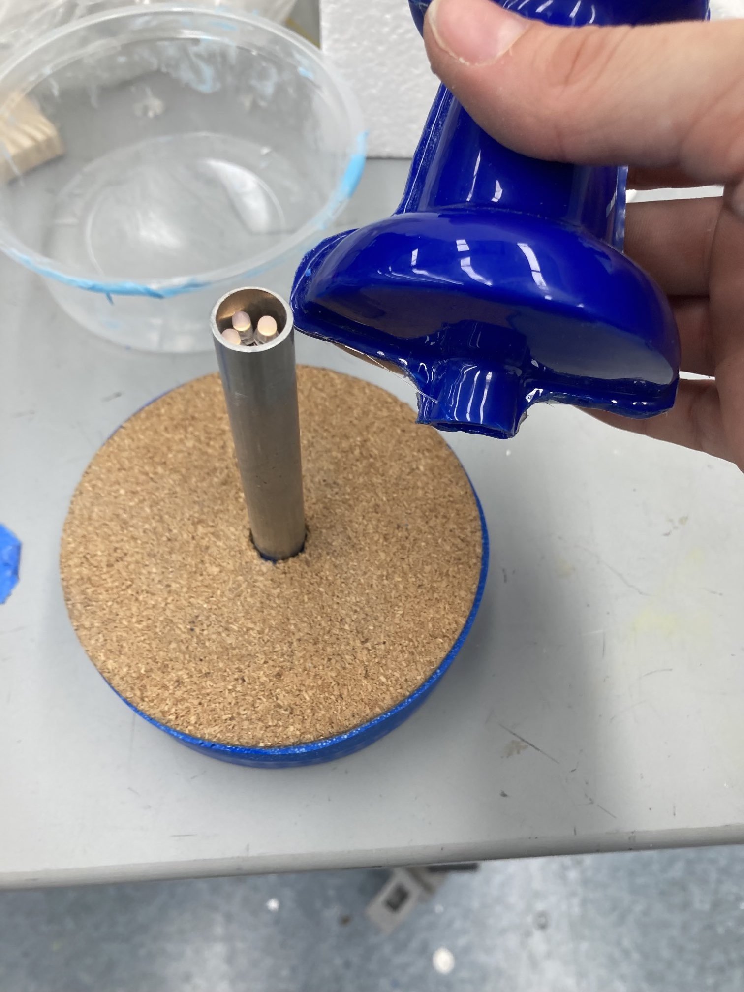
The stock PCB was modified to add wire extensions between the board and the LEDs. Each LED was supplied with a power wire, and they all shared a ground wire to limit the number of wires that needed to be run through the aluminum tube. This limited wire count allowed for all of the wires to be soldered together before running through the tube so that the soldering could all happen before the final product assembly. All of the wires were twisted together and ran through the tube as one larger packet.
In the final assembly, the cork circle was affixed to the top of the base, then a hole was punched in the center for the aluminum rod to pass through. The aluminum rod was press-fit into the base. The pinhead was glued onto the top of the aluminum rod with the LEDs concealed right below the rim of the aluminum piece.
Vacuum Forming Process


Cutout and Sand Blasted Pin Halves

Cyanoacrylate Glue Up

Trimmed Seam Lines and Assembled
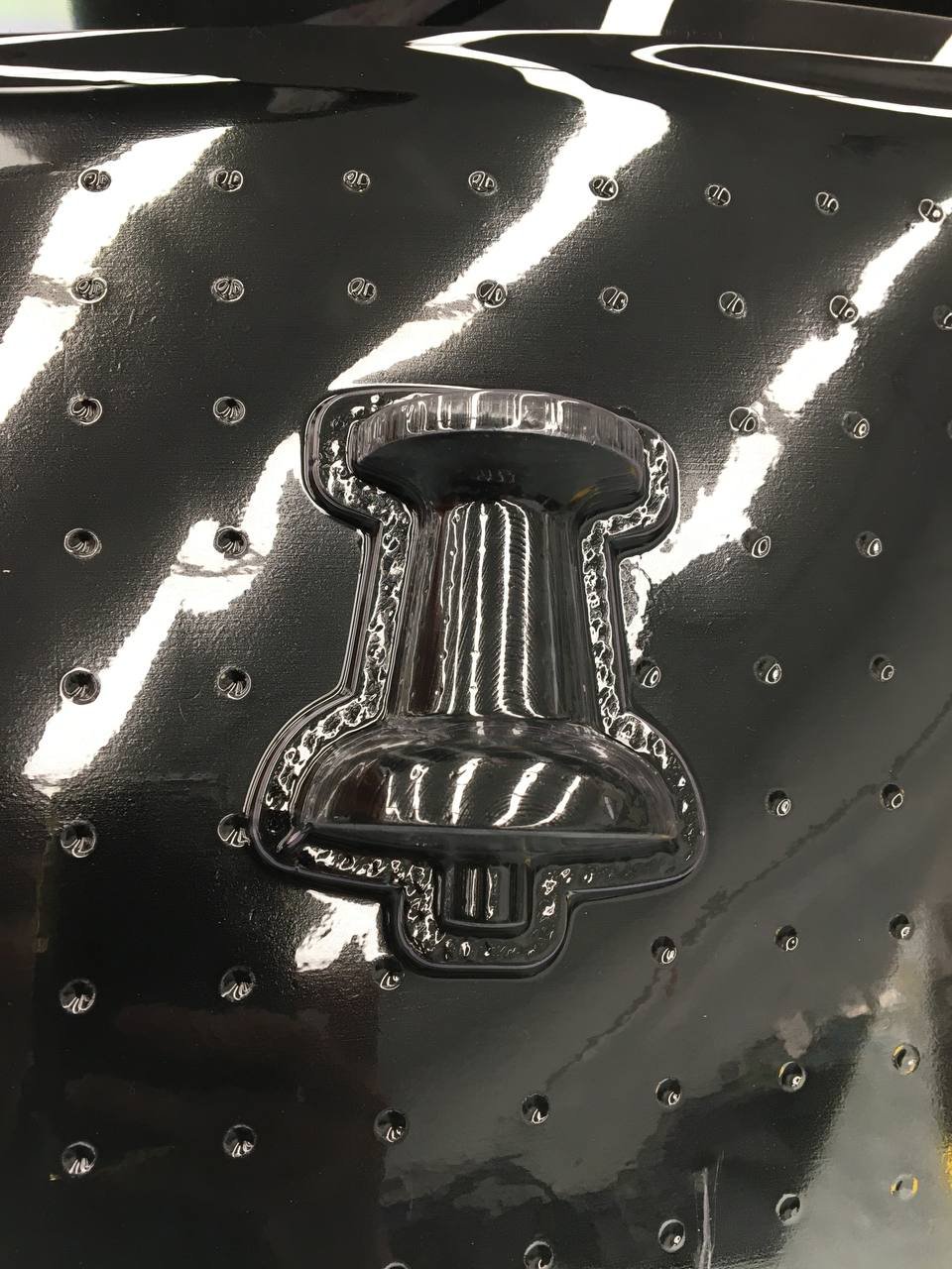
3D Printed ABS Thermoform Mold
Vacuum Formed PETG
Formed Part before Cutting
Design For Manufacturing
Limited Part Count
The bottom cover is designed with flexible tabs, enabling the buttons to be pushed through the cover without requiring additional components. The buttons on the PCB were not longer than the battery housing so simple holes in the bottom of the housing would not have enabled this access.
Obvious Asymmetry
In the final fabrication, an alignment groove was integrated into both the bottom of the main base and the bottom cover. This strategic addition serves a dual purpose. Firstly, it provides a clear visual indication, ensuring the proper orientation for aligning and attaching the bottom cover to the main base. Secondly, the alignment groove enables the insertion of a tool between the two parts, facilitating their separation during disassembly.
Single Part Mold
Both cast parts were both originally designed with a central parting line. However, challenges with air bubbles and mold sagging with the large flat parts prompted a design modification. We simplified both parts and switched to a one-part mold which enabled easier venting and reduction in the casting process complexity.
Cork Topper
The top surface of the lamp base was covered with a piece of cork. This strategic addition allowed for a one-part molding process to be used for the base by covering the inferior surface finish that resulted from the open side of the mold. We increased the diameter of the base to match the dimensions of commercially available sticky cork circles, eliminating the need for a custom cork shape. This reduces costs and streamlines the production process without compromising the functionality or aesthetics of the final product.
Post Processing Holes
We faced challenges casting parts with small through holes, as the silicone tore in the long narrow sections needed to create holes in the final urethane parts. We addressed this by replacing small through holes with small alignment indents in the mold blanks. The indents enable us to accurately drill holes in the correct positions after the part is fully cured.
Limited Fasteners
Originally, the main base, PCB, and bottom cover were intended to be fastened together using threaded inserts, held in place by machine screws. This single set of fasteners to join all three parts maintains the ability to disassemble the lamp while reducing the need for multiple sets of fasteners. However, during the fabrication process, shrinkage in the curing urethane resulted in tighter part dimensions than initially anticipated. Consequently, a press-fit method was utilized to secure the bottom cover in place without the need for additional fasteners.
Bottom Cover Casting Process
Failed Two-Part Mold


In our first attempt at making a silicone mold, the defects included the silicone sticking to 3D prints because of their rough surface, air bubbles in the silicone, and air bubbles within the urethane creating open cavities in the final part
Successful Single Part Mold


Manufacturing Report
Improvement Opportunities
To improve the manufacturability of the lamp the following changes could be made:
Source pre-wired LEDs to reduce the assembly time.
Create a die to quickly and precisely cut out the two halves of the pin from the remaining plastic sheet.
Create a Jig to hold the two pin halves together while gluing to ensure alignment and reduce assembly time.
The PCB could be moved to the head of the pin fully eliminating the need for a base or wire extensions on the LEDs. This would also allow the pin to be stuck anywhere which would align well with the brand identity goals.
Collaboration
During the GlowPin project, collaboration with fellow student Jay Chomowitz significantly bolstered our efforts. Jay made substantial contributions to the CAD design, and played a pivotal role in the 3D printing of molds, vacuum forming, and performing the analysis within the bill of materials. Notably, our collaboration extended to the sharing of CAD files and the Bill of Materials, ensuring consistency and alignment between our respective reports. This partnership was instrumental in combining our skills and efforts and enabling us to learn from each other’s unique skillsets.
